Blog #6
Remote-Controlled Garden Seeder
Team 31- Beyza Kural, Syed Hussain, Nawaf Abulhaija
Progress Update 2/4/2024 - 02/17/2024
During the work period of February 4th – February 17th, our team worked on completing the disassembly of the children's ride-on toy. We finished taking apart all of the components until we had the two drive motors, the tires, the axle, and the battery separated which are shown in Figures 3, 4, and 5, respectively. As previously mentioned, the motors are already geared to our desired speed so that will save our team both time and cost. After analyzing the aluminum frame of the ride-on toy, we decided that it would be best to use Aluminum 6061 which has high corrosion resistance and will be most optimal for our device's intended uses. We had 4 rods cut to our specific dimensions to make the frame, as shown in Figure 5, and these were purchased from a local metal shop. Since our last progress report, our team considered welding the 4 rods together, however, we decided to go with bolting them together since it would be more cost-effective and our device does not have any critical areas that would need to be welded.
Currently, our team is working on the component layout within the aluminum frame. We are considering what would be the best way to place the parts without interfering with the tires while also ensuring that the device can perform its tasks optimally. Therefore, our team is developing the dimensions needed for the aluminum sheet that will house all of the components that will be sourced from the same metal shop previously mentioned. Since the last progress report, our team has conducted research on various methods of implementing a turning mechanism into a device such as ours. During the disassembly, we obtained the turning rod from the ride-on vehicle which is shown in Figure 2. After looking into a few options, we ordered an actuator that would essentially be attached to the mainframe through a bracket and at the same time, would also be connected to the turning rod. The actuator acts as a link between one side of the tire and the other so that when the user indicates a turn through the remote control, the actuator will be able to send the signal to the turning mechanism. Another component that we looked into during this work period was the electronic speed controller (ESC) which will control the amount of voltage going to the motor. The ESC takes a signal from the controller, so the more the controller is pushed, the more voltage there is that goes from the battery to the motor. When this part arrives, we will need to connect it with all our other electrical components to ensure that they are all in conjunction with one another.
For the work period of February 17th through March 9th, our team will be focused on completing the full assembly of our device. As we are receiving our last few shipments of the remaining parts, we are meeting regularly to ensure that all potential obstacles have a backup plan. We will meet at least 2-3 times a week for the next 2 weeks for the building phase which we originally projected to complete by March 15th. We are currently on track with this fifth milestone and we plan to have our all components assembled to the main structure and complete all electrical components to the battery, remote control, actuator, and ESC.

Figure 1. Disassembled Ride-on Toy Base

Figure 2. Turning Rod
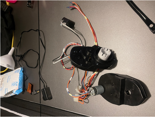
Figure 3. Drive Motors

Figure 4. Tires and Axle

Figure 5. Battery and Aluminum 6061 Rods
In the upcoming two weeks, as we assemble the device, we anticipate a challenge related to attaching the aerator to the rear of the device, potentially leading to poor turning performance. Additionally, this connection could result in constant soil aeration, which may not always be desirable. To address these issues, one proposed solution is to implement a pin-based connection system between the aerator and the device. This design would allow users to easily detach the aerator when it is not needed, thus preventing constant aeration and potential turning difficulties.
We may also encounter an issue with integrating and synchronizing all the electrical components of the device, including coding the actuator and hopper since it is not our strongest skill. To overcome this, we plan to seek advice from our advisor. His expertise and recommendations will be invaluable in ensuring that all electrical components work well together, optimizing the device's overall performance.
Another challenge we may face during the assembly process is maintaining the structural integrity of the device. While we are confident in our ability to construct a structurally sound frame, potential issues could arise during the bolting of the steel frame and the addition of all the components onto it. To mitigate these concerns, we plan to distribute the load evenly across the frame. This approach will help prevent any bending or distortion of the structure over time, ensuring its long-term stability and functionality.


Comments
Post a Comment